Parameter und Auswahl von Spannungsstabilisierungsdioden
"As a hardware engineer, have you ever experienced such moments:
You were looking for a SOD-323 package, 15V Zener diode, and at the same time, you opened the data sheets of several manufacturers. Comparing IR (reverse leakage current) and Pd (power consumption), your eyes were almost blinded;
Finally, you decided to use BZX84C5V1, but your purchasing colleague suddenly said 'out of stock', suggesting to switch to MM3Z5V1. Your heart tightened immediately: Can these two directly replace each other?
The parameters of voltage regulators are numerous, and the part numbers are countless. Many engineers are not ignorant of the principles, but they are stuck by the 'last mile' of selection implementation. This article directly clarifies the core parameters and packaging correspondences of the mainstream series for you. Spend 10 minutes reading it, and the next time you make a selection, you can save at least half a day spent searching through the Data Sheet."
A、The core value of a Zener diode
Definition in one sentence: A voltage stabilizing diode (Zener diode) is a special type of diode that operates within the reverse breakdown region. Its main function is to provide a highly stable output voltage when the input voltage fluctuates or the load changes.
Why is it important?
In electronic systems, power fluctuations can cause chips to malfunction, data loss, and even hardware damage. The voltage stabilizing diode acts as the "voltage stabilizer" of the circuit, ensuring that critical modules (such as MCUs, ADCs) always operate within a safe voltage range.
Example: In a mobile phone charger, a 5.1V voltage stabilizing diode ensures that the USB interface outputs a constant 5V, preventing the device from being damaged by overvoltage.
The Zener diode is derived from the name of a person named Zener and is also known as a Zener diode. It has similarities to the transient suppression diode mentioned earlier.

Zener diode packaging illustration

B、Working Principle: From "Reverse Breakdown" to "Voltage Stabilization
2.1 Ordinary Diode vs Zener diode (Key Differences)


2.2 Detailed Explanation of Reverse Breakdown Mechanism
l Avalanche Breakdown (>6V): High reverse voltage accelerates electrons, causing collisions that generate a large number of free electrons. The current surges sharply while the voltage remains nearly unchanged.
l Zener Breakdown (<5V): A strong electric field directly tears valence electrons free, forming a current with a stable voltage.
Imagine a river (input voltage) flowing through a "water gate" (Zener diode):
l When the water level (voltage) is below the threshold → the water gate closes, and no water flows (no current).
l When the water level exceeds the threshold (Vz) → the water gate automatically opens to release water, and the water level (voltage) is always maintained at the threshold.
Before breakdown, the Zener diode has a very high resistance. After the breakdown, its resistance drops rapidly to a very low value. Subsequently, the current increases while the voltage remains constant.
Zener diodes are categorized by their breakdown voltage, which is related to the doping concentration of the PN junction.
Due to this characteristic, Zener diodes are mainly used as voltage regulators or voltage reference components.
Zener diodes can be connected in series for use at higher voltages, and more stable voltage values can be obtained through series connection. Parallel connection is not allowed.
In most cases, they are used in applications where high voltage accuracy and power are not required. For high-precision scenarios, voltage reference chips are selected; for high-power applications, dedicated power supply chips are chosen.
2.3 Voltage-Current Characteristic Curve

Stabilization zone: When V ≥ Vz, the current changes from Izmin to Izmax, while the voltage Vz remains almost constant (ΔV ≈ 0)
C、Performance Characteristics: How Parameters Affect Voltage Regulation Performance
(I) Core Voltage Regulation Parameters (Determine "How Stable the Voltage Is")
1. V Z (Zener Voltage)
Meaning: This is the most critical parameter of a Zener diode. It refers to the voltage across the Zener diode when the current flowing through it reaches the specified test current (IZT).
Simple Understanding: Think of it as the diode's "ID number". For example, a diode labeled 5.1V will have a VZ of approximately 5.1V.
Note: VZ is not an absolutely fixed value, but a range (e.g., 4.8V~5.4V), which depends on the accuracy class (±5% or ±1%).
2. IZT (Test Current)
Meaning: The standard current value used by manufacturers when measuring VZ and the dynamic resistance ZZT.
Engineering Significance: This is the operating point where the Zener diode performs optimally and most stably. When designing circuits, the operating current of the Zener diode should be kept as close to this value as possible.
Example: The IZT of a 1N4733A (5.1V) is typically 49mA. If you operate it at 5mA, it can still regulate voltage, but its accuracy will degrade.

3. VZK (Zener Voltage at Knee)
Meaning: The voltage across the Zener diode when the current decreases to a very low level (i.e., IZK). At this point, the V-I characteristic curve begins to bend, resembling a human knee.
Characteristic: VZK is typically 5%~10% lower than the nominal Zener voltage VZ.
Application: In low-power standby mode, if the current is very small, the output voltage will drop to VZK instead of VZ. This must be considered when designing low-voltage systems to prevent voltage insufficiency from causing system reset.
(II) Limit & Safety Parameters (Determine Safe Operating Range)
These parameters determine whether the Zener diode will burn out and serve as the redline for circuit design.
4. PZM (Maximum Power Dissipation)
The maximum power at which the Zener diode can operate stably. Exceeding this value may cause device damage.
Formula: PZM=UZ×IZMax
where IZMax is the maximum Zener current.
Common ratings: 0.2W, 0.3W, 0.5W, 1.0W, 1.5W, 3W, 5W, etc.
Design principle: Actual operating power should be limited to 50%~70% of PZM to provide a safety margin.
5. IZM (Maximum Zener Current)
Definition: The maximum current allowed to flow through the Zener diode without exceeding its maximum power dissipation PZM.
Formula:I ZM≈ PZM / Vz
Consequence: If the current exceeds IZM, the Zener diode will burn out instantly (open or short circuit).
6. IZK(Knee Current)
Definition: The minimum current required for the Zener diode to maintain basic voltage regulation. Below this current, regulation fails, and voltage varies drastically with current.
Relationship: IZK is usually much smaller than IZT (about 1/10 of IZT or less).
Design pitfall: Many circuits fail under no-load or light-load conditions because the current-limiting resistor is too large, causing the operating current to drop below IZK.
7. IR (Reverse Leakage Current)
Definition: The small current that flows when the reverse voltage applied to the Zener diode is below its breakdown voltage (typically VR).
Characteristic: Ideally zero, but actually exists at the microampere (µA) level.
Importance: Battery-powered devices: Excessively high IR causes rapid standby power consumption.
High-temperature environments: IR increases sharply (often dozens of times) as temperature rises.
8. VR (Reverse Voltage)
Definition: The voltage applied by manufacturers when measuring reverse leakage current IR.
Relationship: VR is usually set to a value lower than VZ (e.g., for VZ = 5.1V, VR may be 1V or 3V). No breakdown should occur at this voltage.
(III) Dynamic Performance Parameters (Determine Regulation Quality)
These parameters determine the Zener diode’s ability to suppress voltage fluctuations and noise.
9.ZZT (Dynamic Impedance at Test Current)
Definition: The ratio of voltage changes to current change (ΔV/ΔI) at the rated test current IZT.
Physical meaning: Smaller is better!
The smaller ZZT is, the more stable the voltage remains as current changes. Typical values: a few ohms to several tens of ohms.
Application: Used in calculating power supply ripple.
![]()
10.ZZK(Dynamic Impedance at Knee Current)
Definition: Dynamic impedance at the minimum current IZK.
Characteristic: Very large (hundreds to thousands of ohms).
Conclusion: Under light-load conditions (near IZK), the Zener diode has very poor noise immunity, and the output voltage is easily affected by interference.
(IIII) Environmental Characteristics (Determine Temperature Sensitivity)
11. IZTC (Zener Impedance Temperature Coefficient)
Unit:mV/℃ or % / ℃。
Meaning: The magnitude of the change in Zener voltage VZ for every 1℃ change in temperature.
Temperature Drift Rule (Critical)
- VZ<5V: Dominated by Zener breakdown, negative temperature coefficient (temperature ↑, voltage ↓).
- VZ>7V: Dominated by avalanche breakdown, positive temperature coefficient (temperature ↑, voltage ↑).
- 5V<VZ<7V: Two effects cancel each other out, temperature coefficient near zero (most stable).
Golden Rule for Selection
For precision voltage reference applications, Zener diodes around 6.2V are preferred, as they exhibit the smallest temperature drift and highest stability.

D、Practical Selection Logic Chain
When you review a Zener diode datasheet, follow this logical sequence:
1. Check VZ: Is it the voltage I need? Is the accuracy (±5%) sufficient?
2. Check PZM: Will the maximum current in my circuit multiplied by the voltage exceed this value? (Safety first)
3. Check IZT and ZZT: Can the current I design be close to IZT? This ensures the best regulation performance and minimum ripple.
4. Check IZK: Under minimum load conditions, will the current drop below IZK? If so, the voltage will collapse.
5. Check IZTC: Will the product be used outdoors? Is the temperature variation large? If yes, should I switch to a 6.2V device or apply temperature compensation?
6. Check IR: For battery-powered applications, will this leakage current drain the battery within a few days?
E、Main Application Circuits of Zener Diodes

F、Parameter Calculation: From Theory to Practical Design

1 Current-Limiting Resistor Calculation
R = (Vin - Vz) / (Iz + IL)
Which:
IZ = Zener diode current (must be between IZmin and IZmax)
IL = Load current = VZ/RL
2 Calculation Steps (with Example)
Design Goal: 5V voltage regulator circuit
- Input voltage Vin = 12V (fluctuation range: 10V ~ 15V)
- Load resistance RL = 250Ω (maximum load current ILmax=5.1V/250Ω≈20.4mA)
- Zener diode model: 1N4733A (VZ=5.1V, IZT=50mA, PZM=1W)

Calculation Process:
1. Determine the range of IZ:
Izmax = Pzm / Vz = 1W / 5.1V ≈ 196mA
Izmin = 5mA(typical value, refer to the datasheet)
→ Iz range:5mA ~ 196mA
2. Calculate the current-limiting resistor R:
Minimum R value (to ensure IZ does not exceed IZmax when Vin=15V, IZ and IL are at maximum):
R_min = (15V - 5.1V) / (196mA + 20.4mA) ≈ 9.9V / 216.4mA ≈ 45.7Ω
Maximum R value (to ensure voltage regulation is maintained when Vin=10V, IZ and IL are at minimum):
R_max = (10V - 5.1V) / (5mA + 0mA) = 4.9V / 5mA = 980Ω
→ R should be selected between 45.7Ω ~ 980Ω. A standard value of 220Ω is chosen (balances efficiency and stability).
3. Verify power dissipation (maximum power point):
Vin=15V, R=220Ω
I_total = (15-5.1)/220Ω ≈ 45mA
Pz = Vz × Iz = 5.1V × (45mA - 20.4mA) ≈ 5.1V × 24.6mA ≈ 0.125W(This is well below PZM=1W, so it is safe.)
✅ Design Conclusion:R=220Ω,Zener diode choose 1N4733A(5.1V/1W),covering the input voltage range of Vin=10V~15V.
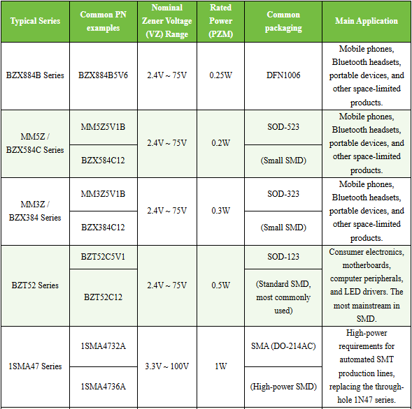
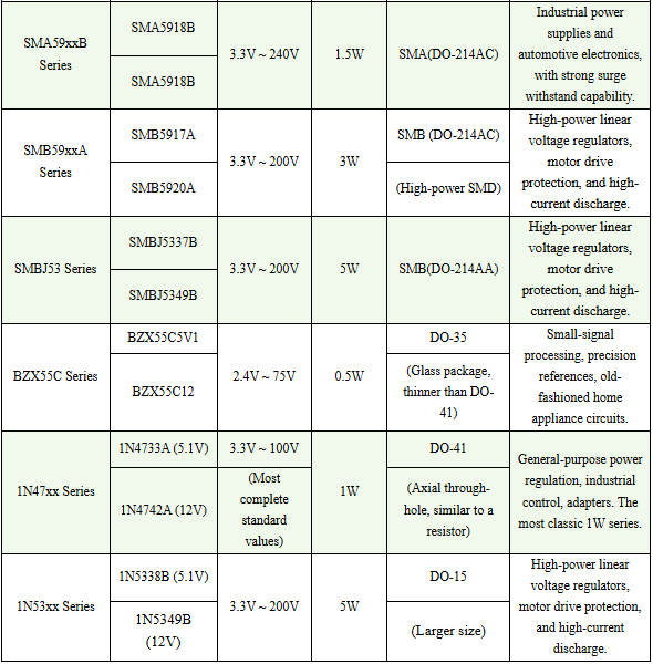
G、Quick Reference Table: Common Models, Packages & Power Ratings of Shanghai Leiditech Zener Diodes