
Overview of 7D Intelligent Disassembly AI Robot and EMC Protection —— Shanghai Leiditech‘s contributions of years of technical expertise

AI robots are evolving into intelligent terminals that integrate perception, decision-making, execution, multi-modal fusion processing, and self-learning adaptation.
The evolution of robots requires the support of Industry 4.0/5.0/6.0 and advances in semiconductor technology.
Chip manufacturing processes have evolved from 28nm down to 7nm, and their ESD tolerance thresholds have correspondingly dropped sharply from 2kV to below 500V, making them increasingly fragile.
Real-time buses such as EtherCAT have broken through 1Gbps in data rates, narrowing signal margins. The superposition of motor start/stop in workshops, human touch ESD, and cable-coupled interference makes failure issues increasingly prominent.
According to failure statistics from industrial sites, over one-third of abnormal AI robot stoppages are caused by ESD. Typical failure modes include main controller lock-up, encoder servo step loss, and high-speed communication bus disconnection.
GB/T 38326-2019 General EMC Requirements for Industrial Robots has been formally implemented, mandating power port surge test levels of 2kV line-to-line and 4kV line-to-ground, imposing stringent constraints on the design of the complete protection circuit。
The Leiditech EMC engineer, with 16 years of deep experience in the EMC protection field, will deconstruct robotic intelligent applications across seven dimensions in this article. Combined with Leiditech's long-accumulated four major knowledge libraries, this article delivers a full-link ESD and surge protection solution that can be directly referenced and implemented.
Dimension 1: Power Supply
The power supply dimension covers four core areas: 800V AIDC high-voltage power supply, battery BMS management, multi-energy coordination, and high-efficiency monitoring protection communication interaction.
Refined power flow: main control power supply, system 48V DC bus, servo joint power supply, and 24V auxiliary power supply for sensors.
The power flow path is the primary channel for electromagnetic interference. Grid fluctuations in workshops, servo regenerative braking back-EMF, start/stop of adjacent high-power equipment, and dv/dt spikes generated by high-speed SiC switching are all conducted along the power lines, easily damaging MOSFETs, the main control PMIC, and sensor power chips.
1.1 EMC Failure Pain Points Specific to the Power Supply Dimension
(1) 800V AIDC applications: Voltage fluctuations make protection difficult. Huawei uses a ±400V scheme with +400V, -400V, and a floating neutral, powered by three lines, using two MOVs rated at 400V+ connected between +400V and neutral, and -400V and neutral respectively. Delta uses both ±400V and 800V, employing two 400V MOVs and an 800V-rated MOV respectively.
(2) 48V heavy-load joints: Instantaneous high-current turn-off generates avalanche energy; conventional TVS devices with insufficient surge capability are prone to failure.
(3) BMS: Weak voltage and current signals are collected; power-coupled interference causes battery sampling distortion, leading to false triggering of overcharge and over-discharge protection.
(4) Multi-energy grid-connected operation: Ground potential differences between different power modules create common-mode surges, damaging power communication interfaces.
(5) SiC servo switching frequency exceeds 100kHz, dv/dt > 100V/ns: Stray inductance on the bus generates voltage spikes; combined with regenerative braking back-EMF, the instantaneous bus voltage can exceed 60V.
1.2 Leiditech Protection Implementation Solution
(1) 48V servo bus surge protection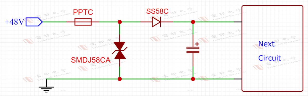
A. Light-load joints (up to 100W): Use SMAJ58CA bidirectional TVS, 400W, for bus surge discharge.
B. Medium-power joints (200~300W): SMBJ58CA, 600W, to handle frequent start/stop surges.
C. Heavy-load 500W joints / main system bus: 5.0SMDJ58CA, 5000W high-power TVS, 104A peak current, passes ±2kV surge testing.
D. Layout requirement: Place TVS at the front end; control TVS and capacitor lead inductance to <10nH to prevent secondary voltage overshoot.
(2) MOSFET drain-source avalanche absorption
|
Model |
NMOS Parameters |
PMOS Parameters |
Comprehensive evaluation |
Recommended Applications |
|
LM3D40NP02 |
20V,40A, Rds(on)=5.3 mΩ |
-20V,-30A, Rds(on)=10.5 mΩ |
✔High cost-effective all-rounder - Low conduction loss (especially NMOS) - Supports medium to high current output - Compact package, PDFN3x3 |
Medium-power joints (e.g., forearm, wrist) |
|
LM4606 |
20V, 7A, Rds(on)=13 mΩ |
-20V, -6A, Rds(on)=30mΩ |
✔Representative of miniaturized low power - Maintains good conduction characteristics at low currents - SOP-8 package |
Micro servos, sensing joints, consumer robot components |
|
LMAK68NP04 |
40V, 68A, Rds(on)=4.5mΩ |
-40V, -47A, Rds(on)=12mΩ |
✔High-voltage high-current workhorse - High power density, suitable for high-torque joints - TO-252-4 package |
High-power joints (e.g., waist, thigh, hip)Applications requiring impact loads or regenerative braking |
(3) Three-phase inverter bridge: Connect TVS in parallel for voltage clamping,combined with an RC snubber circuit to suppress SiC ringing.
(4) Gate drive fine protection: Connect SMBJ18CA in parallel between gate and source to clamp the gate voltage to ±25V, preventing gate oxide breakdown.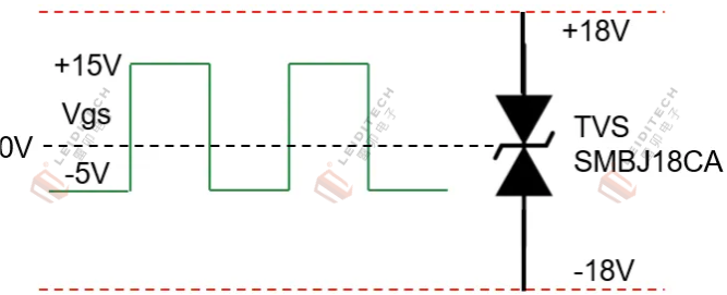
(5) 24V auxiliary power supply / IO-Link sensor power supply
A. Adopt a three-layer architecture of "TVS + PPTC + reverse polarity protection": SMDJ33CA for overvoltage clamping, SMD1812 resettable fuse for current limiting, and SK56C Schottky / high-power PMOS for reverse polarity protection, suitable for robot end-effector sensor power supply scenarios.
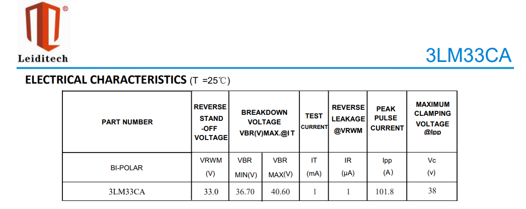
B. 3LM33CA (SMC package): Vrwm = 33V, clamping voltage as low as 38V, 3000W power. The low clamping advantage allows the downstream DC-DC voltage rating to be reduced from 60V to 40V, directly lowering overall BOM cost; a single device can pass 3kV differential mode surge, meeting IEC 61000-4-5 Level 4, line-to-line 2kV.

(6) BMS sampling low-voltage protection
Connect the low-junction-capacitance SD12C in series with a current-limiting resistor to isolate high-level bus interference from entering the millivolt-level sampling loop, preventing battery monitoring data drift.
Dimension 2: Vision
The robot's "eyes" encompass ultra-high-precision perception, real-time 3D reconstruction, dynamic behavior analysis, multispectral imaging, motion scene prediction, and holographic human-machine interaction.
The hardware carriers of the vision system include Gigabit EtherCAT vision buses, 23-bit encoders, RGB-D cameras, LiDAR, and teaching touchscreens. All of these belong to high-speed weak signal links, which are sensitive to junction capacitance and have extremely low voltage tolerance.
2.1 EMC Failure Pain Points Specific to the Vision Dimension
(1) 1Gbps EtherCAT vision bus using high-capacitance ESD causes signal eye diagram closure, communication jitter soaring from 1μs to hundreds of microseconds, resulting in vision positioning drift.
(2) Differential millivolt-level encoder signals are susceptible to ESD coupling, causing joint positioning errors >0.01° and a sharp drop in precision assembly yield.
(3) ESD strikes on the teaching touchscreen affect the touch controller, causing touch malfunction and display artifacts.
(4) The photosensitive chip in multi-spectral cameras has an HBM tolerance of only 500V; even minor ESD can cause imaging noise or black screen.
2.2 Leiditech Protection Implementation Solution
(1) Gigabit EtherCAT master/slave stations
For the differential signals on the main controller network port, the GBLC03C is recommended, with 0.6pF ultra-low junction capacitance and ±30kV ESD, ensuring 1Gbps signal integrity. On the PCB, the ESD device must be placed within 5mm of the network port, with a complete ground plane and multiple vias for ESD discharge, to prevent residual voltage elevation caused by long traces.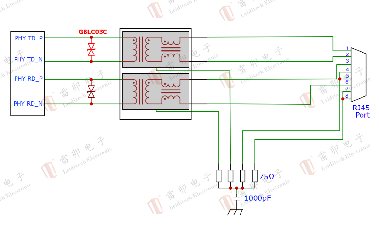
(2) 3.3V low-speed I/O for cameras and teaching touchscreens
For SPI/I2C image control buses, use the SMC33, with junction capacitance ≤45pF, meeting IEC 61000-4-2 Level 4, withstanding ±30kV contact discharge.
(3) LiDAR signal protection
For the signal side, use the GBLC03C (0.6pF) ultra-low capacitance ESD to balance ranging accuracy and ESD immunity.
Dimension 3: Hearing
The hearing system undertakes ultra-sensitive sound capture, environmental noise analysis, non-speech intelligent recognition, real-time noise filtering, emotional intent judgment, and equipment fault acoustic monitoring. Application scenarios include workshop abnormal sound detection, collaborative robot voice interaction, motor bearing abnormal sound diagnosis, and safety alarm acquisition.
The hearing system uses weak analog small signals, making it highly susceptible to servo PWM high-frequency noise and human-body ESD interference.
3.1 EMC Failure Pain Points Specific to the Hearing Dimension
Servo parasitic currents (0~6MHz) and bearing discharge pulses (40~80MHz) can couple into the audio acquisition loop, causing a surge in pickup noise floor and false abnormal sound alarms; long microphone lines can couple ESD, causing operational amplifier latch-up failure and interrupting sound acquisition.
3.2 Leiditech Protection Implementation Solution
(1) Microphone analog input: Use the ULC0511CDN30 with 0.22pF low-capacitance ESD, in series with a 1kΩ current-limiting resistor and in parallel with a filter capacitor, to suppress high-frequency pulse interference without compromising audio amplitude.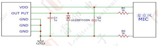
(2) Analog audio: Use the low-junction-capacitance dual-channel integrated LCC05DT3 protection device for ESD protection to save space, or use single-channel options such as ULC0542C or ESD5Z5CL in various packages, meeting IEC 61000-4-2 Level 4.

(3) Long-line RS485 link monitoring: Leiditech uses the low-residual-voltage TSS P0080SC to effectively protect RS422/RS485 chips. The TSS has a nanosecond-level response time, providing both surge and ESD protection while ensuring signal integrity. It meets IEC 61000-4-2 ESD Level 4 with contact discharge of 15kV and air discharge of 8kV, and IEC 61000-4-5 surge 10/700μs at 6kV.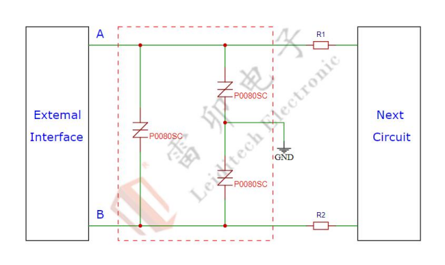
Dimension 4: Smell
The olfactory system relies on high-precision gas sensors to achieve environmental quality monitoring, covering industrial explosion protection, medical disinfection, agricultural gas detection, and smart home integration.
The hardware for the olfactory system is mostly two-wire 4-20mA loop transmitters. Long-distance wiring and low loop power consumption are the core constraints, and the protection circuit must not introduce additional voltage drops or leakage currents.
4.1 EMC Failure Pain Points Specific to the Olfactory Dimension
Power cable-induced surges, human-body ESD, and EFT pulses superimpose, causing gas concentration reading drift and sensor burnout. The loop only has a basic working current of 4-20mA; traditional high-capacitance protection devices will increase static power consumption, and the sensor may fail to start due to insufficient low voltage.
4.2 Leiditech Protection Implementation Solution (Clamping + Current Limiting + Rectification + Filtering)

ESD protection core:
(1) For standard 24V transmitters, use GBLC24C (0.6pF).
(2) For 36V wide-voltage applications, use LC36CI, with ultra-low junction capacitance that does not alter the loop current.
(3) The complete solution passes IEC 61000-4-2 Level 4 ESD, suitable for 4-20mA loop-powered transmitters in lithium battery, chemical, and welding workshop monitoring.
Dimension 5: Taste
Taste system application scenarios include food sorting, pharmaceutical quality inspection, water quality testing, etc.
The taste system relies on high-precision taste analog sensors, outputting microvolt-level analog signals, using 4-20mA loop or 0~5V analog acquisition. It shares the analog protection logic with the olfactory system, but with even lower signal amplitudes, requiring stricter parasitic parameter control.
5.1 Leiditech Protection Implementation Solution
(1) For 0~5V micro-level taste acquisition channels: Use ULC0511CDN30 with 0.22pF ultra-low capacitance ESD, compatible with ADC chip acquisition precision.
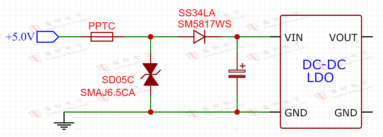
(2) Add SD05C to the onboard ADC power supply to prevent power supply noise from coupling, ensuring taste sampling accuracy and keeping results free from electromagnetic interference.
(2)
Dimension 6: Body
The body system includes joint servos, end effectors, multi-mode mobile chassis, etc.
The body system relies on SiC servo drives, IO-Link joint sensors, 24V digital I/O, force transmitters, motor bearings, etc. The coexistence of strong interference sources and sensitive components makes this the dimension with the most concentrated EMC conflicts in the entire system.
6.1 EMC Failure Pain Points Specific to the Body Dimension
(1) Static PWM parasitic interference: 0~6MHz common-mode currents couple into encoders and force sensors, causing servo step loss.
(2) Dynamic bearing high-frequency discharge: Oil film suspension during motor operation accumulates induced electromotive force that breaks down air, generating 40~80MHz high-frequency pulses that directly damage 7nm-process control chips.
6.2 Leiditech Protection Implementation Solution (Source Suppression - Path Blocking - Terminal Protection)
(1) Power source filtering: Add TVS + common-mode choke + X/Y capacitors to the servo drive output to smooth PWM voltage edges, reduce dv/dt, and attenuate 0~6MHz parasitic common-mode currents.
(2) Path blocking: Install high-permeability ferrite beads at both ends of power cables and encoder cables to create high-impedance paths for 40~80MHz frequencies, preventing cable radiation and conducted interference from reaching the terminal sensors.
(3) Standardized component selection for terminal multi-interface protection.
A. IO-Link three-wire sensors: Power uses SMBJ33CA + PPTC + reverse polarity protection, with SMC12 for I2C/SPI line ESD protection.
B. End-effector 24V digital I/O ports: SMC12 integrated ESD, withstanding ±30kV ESD, suitable for pneumatic grippers and quick-change devices.
C. FlexRay joint real-time bus: SMC27LVQ (5pF) low-capacitance ESD to ensure stable 20Mbps control signal transmission.

Dimension 7: Mind
The mind system carries autonomous learning, emotional interaction, creative reasoning, multi-modal perception fusion, and safety ethics decision-making. The mind system relies on the main control FPGA, AI inference chips, DDR memory, storage modules, and multi-bus protocol processing units. With chip processes of 7~28nm and ESD tolerance as low as 500V, it is the most vulnerable electromagnetic sensitive area of the entire system.
7.1 EMC Failure Pain Points Specific to the Mind Dimension
ESD on high-speed buses such as EtherCAT/CAN-FD, servo-conducted surges, and ground potential fluctuations can easily cause main controller lock-up, logic errors in inference, and memory data loss. High-speed SerDes and DDR signals are extremely sensitive to junction capacitance; conventional protection devices directly cause computational communication speed reduction and stuttering in image AI inference.
7.2 Leiditech Protection Implementation Solution
(1) High-speed computing buses (SerDes/DDR/Gigabit Ethernet)
Leiditech recommends the ultra-low capacitance ULC1811CDNQ / ULC15CTNQ (0.3~0.6pF), which stays below the chip's withstand voltage threshold while balancing protection and signal integrity.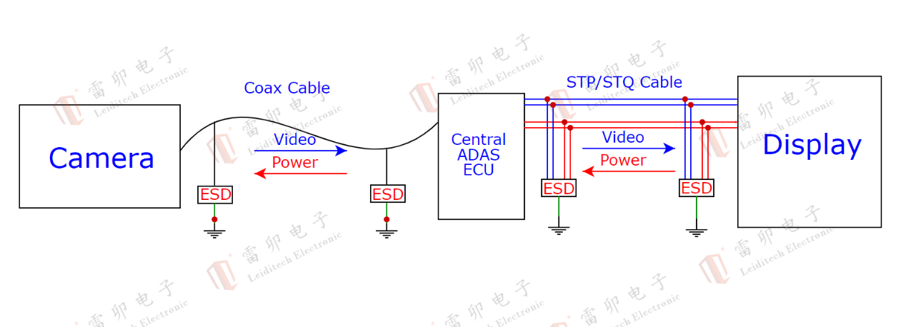
(2) Low-speed control buses I2C/SPI/UART
DFN1006 micro ESDA33CP30 and ULC0542C are suitable for high-density SMD layouts on the main controller, providing UART serial port ESD protection while saving PCB space.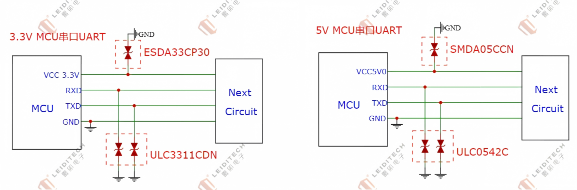
(3) Main controller 48V/24V input power
At the system entry point, use a two-stage protection of "MOV + GDT coarse discharge + high-power TVS fine clamping" to handle lightning-induced surges in workshops, meeting the national standard line-to-ground 4kV test requirement.

(4) PCB mandatory rules: The computing power area must have an independent and complete ground plane, separated from the servo drive area. Critical signal traces must not cross ground plane splits.
8. Seven-Dimensional System Synergy: Three Golden Rules for EMC Protection Component Selection
8.1 Voltage matching first principle
The TVS/ESD reverse stand-off voltage Vrwm must be higher than the normal operating voltage of the line, and the clamping voltage Vc must be lower than the maximum withstand voltage of the downstream chip. For power loops, Leiditech's snap-back TVS can be used to lower the clamping voltage, reducing the downstream DC-DC withstand voltage requirements and overall BOM cost.
8.2 Signal rate - junction capacitance matching principle
(1) Rate > 1Gbps (vision, EtherCAT, SerDes): junction capacitance ≤ 0.5pF.
(2) 100Mbps~1Gbps (CAN-FD, Fast Ethernet): junction capacitance < 5pF.
(3) Analog 4-20mA: junction capacitance can be relaxed to 1~5pF.
(4) Power and low-speed I/O: junction capacitance is not restricted; priority should be given to improving surge current capability.
8.3 Graded discharge principle for high-interference scenarios
For high-power buses, long-distance communication, and welding/stamping high-EMC workshops, use high-power TVS for precision clamping, with series current-limiting resistors between stages for timing coordination, dissipating surge energy progressively. The reliability of this approach is much higher than that of a single-device solution.
9. Leiditech Implementation Support
Shanghai Leiditech is a leading brand in EMC solutions and component supply. After years of accumulation, Leiditech has compiled four major knowledge dictionaries. Feel free to contact us anytime to request them:
9.1 Localization Replacement Dictionary: Leiditech offers compatible replacements for major brands such as NXP, SEMTECH, LITTELFUSE, ON-SEMI, PROTEK, VISHAY, DIODES, ST, TI, ROHM, WE, Tyco, Wurth, and more.
9.2 Protection Solutions Dictionary: Leiditech provides protection solutions for various signal interfaces, power supply voltages, popular modules, and digital sensors.
9.3 Market Mapping Dictionary: Leiditech has market maps for smart automotive, smart home, smart factory, smart city, new energy photovoltaics, smart healthcare, and AI robotics. Click on each product name on the map to view recommended solutions and models.
9.4 "100 Questions and Answers on EMC": This book contains the lifelong accumulation and careful compilation of EMC industry experts. A new edition is scheduled for release in 2026.
Leiditech supplies EMC-related components including TVS, ESD, TSS, PPTC, GDT, MOV, MOSFET, rectifiers, Zener diodes, inductors, and ferrite beads. With dictionary-style knowledge accumulation, a free EMC lab, systematic EMC diagnostic tools and methods, and experienced EMC rectification experts skilled at solving various complex problems, Leiditech can assist customers with forward EMC design.
|
AI Robot Dedicated - Leiditech EMC Component Selection Quick Reference Table |
||||
|
Application location |
Model |
Type |
Package |
Key Parameters |
|
800V AIDC |
20D112K |
MOV |
20D |
1100V,6.5kA |
|
800V AIDC |
20D561K |
MOV |
20D |
560V,6.5kA |
|
800V AIDC |
20D621K |
MOV |
20D |
620V,6.5kA |
|
800V AIDC |
AK3-1000CL |
TVS |
AK3 Blue Baby |
1000V,3kA |
|
800V AIDC |
AK3-460CL |
TVS |
AK3 Blue Baby |
460V,3kA |
|
AC 220V power protection |
14D471K |
MOV |
14D |
470V,Bidirectional,4500A |
|
AC 220V power protection |
20D471K |
MOV |
20D |
470V,Bidirectional,6500A |
|
AC 220V power protection |
25D471K |
MOV |
25D |
470V,Bidirectional,15000A |
|
AC 220V power protection |
2R600-8L |
GDT |
2R 8mm |
600V,Bidirectional,10KA |
|
DC 48V power supply |
SMAJ58CA |
TVS |
SMA |
58V,Bidirectional 400W |
|
DC 48V power supply |
SMBJ58CA |
TVS |
SMB |
58V,Bidirectional 600W |
|
DC 48V power supply |
5.0SMDJ58CA |
TVS |
SMC |
58V,Bidirectional 5000W |
|
DC 24V power supply |
5.0SMDJ33CA |
TVS |
SMC |
33V,Bidirectional 5000W |
|
DC 24V power supply |
3LM33CA |
TVS |
SMC |
33V,Bidirectional,3000W |
|
DC 5V power supply |
SD05C |
ESD |
SOD-323 |
5V,Bidirectional,45Pf |
|
MOS gate protection |
SMBJ18CA |
TVS |
SMB |
18V,Bidirectional,600W |
|
Sampling interface |
SD12C |
ESD |
SOD-323 |
12V,Bidirectional,45pF |
|
Microphone audio |
ULC0511CDN30 |
ESD |
DFN1006 |
5V,Bidirectional,0.22pF |
|
Analog audio |
LCC05DT3 |
ESD |
SOT-23 |
5V,Bidirectional,1.2pF,2-channel |
|
RS232/SPI/I2C |
SMC12 |
ESD |
SOT-23 |
12V,Bidirectional,15A |
|
SPI/I2C |
SMC33 |
ESD |
SOT-23 |
3.3VBidirectional,25A |
|
RS485 interface |
SM712 |
ESD |
SOT-23 |
7/12V,Bidirectional,45pF,17A |
|
RS485 interface |
P0080SC |
TSS |
SMB |
6V,100pF,6kV |
|
Gigabit Ethernet ESD protection |
GBLC03C |
ESD |
SOD-323 |
3.3V,Bidirectional,30A |
|
4-20mA sensor |
GBLC24C |
ESD |
SOD-323 |
24V,Bidirectional,1pF,8A |
|
4-20mA sensor |
GBLC36C |
ESD |
SOD-323 |
36V,Bidirectional,1pF,8A |
|
4-20mA sensor |
S1M |
Rectification |
SMA |
1000V,1A |
|
Flexray |
SMC27LVQ |
ESD |
SOT-23 |
27V,Bidirectional,5pF,3.5A |
|
Flexray |
SMC24LVQ |
ESD |
SOT-23 |
24V,Bidirectional,5pF,4A |
|
MCU UART |
ESDA33CP30 |
ESD |
DFN1006 |
3.3V,Bidirectional,12 pF,8A |
|
MCU UART |
ULC3311CDN |
ESD |
DFN1006 |
3.3V,Bidirectional,0.3PF,5A |
|
MCU UART |
ULC0542C |
ESD |
DFN1006 |
5V,Bidirectional,0.3 pF,8A |
|
SerDes |
ULC1811CDNQ |
ESD |
DFN1006 |
18V,Bidirectional,0.5pF |
|
SerDes |
ULC15CTNQ |
ESD |
DFN1610 |
15V,Bidirectional,0.6pF |
|
MOSFET drain-source avalanche absorption |
LM3D40NP02 |
MOS |
PDFN3x3 |
NMOS:20V,40A, PMOS: -20V,-30A, |
|
MOSFET drain-source avalanche absorption |
LM4606 |
MOS |
SOP-8 |
NMOS:20V, 7A, PMOS: -20V,-6A, |
|
MOSFET drain-source avalanche absorption |
LMAK68NP04 |
MOS |
TO-252-4 |
NMOS:40V, 68A, PMOS: -40V,-47A, |