
Localization of MOSFETs from the Perspective of the LM3401: Key Parameter Comparison, Typical Applications, and a Guide to Avoiding Pitfalls
A client has asked Leiditech to help find an alternative for the Diodes SOT-23 package PMOS (DMG3401LSN). We have selected the LM3401. Can this be used as a direct replacement? How can we ensure a safe substitution? What parameters need to be checked for the replacement?
 |
As the global semiconductor supply chain continues to evolve, the localization of MOSFETs has become a key focus for many electronics engineers and procurement professionals. However, true "pin-to-pin" replacement is far from a simple model-to-model match; it requires a systematic evaluation of electrical performance, thermal safety, and dynamic characteristics. This article takes the Leiditech LM3401 as an example, providing a practical selection reference through in-depth parameter analysis, measured data comparisons, typical applications, and engineering tips for avoiding common pitfalls.
I. Introduction to Key Parameters That Must Be Considered for MOSFET Localization
When selecting a domestic alternative for a MOSFET, it is not sufficient to simply match the nominal voltage and current ratings. A scientific evaluation requires strict attention to the following four dimensions:
1. Basic Static Parameter Matching
l Drain-Source Breakdown Voltage (V(BR)DSS): This is a critical parameter for device reliability. It is essential to ensure that the replacement's breakdown voltage is greater than or equal to that of the original device, with a reasonable derating margin (typically 20%-50% higher is recommended), to handle grid fluctuations or voltage spikes generated by inductive loads.
l Continuous Drain Current (ID): This determines the device's current handling capability. The current ratings under the same ambient temperature must be compared to ensure that the alternative can meet both peak and continuous load requirements, with a safety margin of at least 50%.
l On-Resistance (RDS(on)): This is a core parameter that determines conduction loss and heat generation. It is not sufficient to only look at the typical value at 25°C; special attention must be paid to its performance at high temperatures (e.g., 175°C). As temperature increases, RDS(on) rises, which can create a vicious cycle of heating.
2.Gate Drive and Threshold Characteristics
l Gate Threshold Voltage (VGS(th)): This is the minimum gate voltage required to begin turning on the MOSFET. It is essential to ensure that the replacement's threshold voltage is the same as or close to that of the original device, to avoid false turn-on or incomplete turn-on in low-voltage drive applications.
l Maximum Gate-Source Voltage (VGS(max)): Verify that the maximum control voltage provided by the drive circuit does not exceed the absolute maximum rating of the replacement device, to prevent breakdown of the gate oxide layer.
3. Package and Thermal Design Compatibility
l Power Dissipation (PD) and Thermal Resistance (RθJA): Thermal resistance is key to evaluating heat dissipation capability. Lower values indicate better ability to conduct heat from the chip to the ambient environment. The temperature rise under actual operating conditions must be evaluated together with the PCB copper area used for heat sinking, ensuring that the maximum junction temperature remains well below the absolute limit.
4. Dynamic Switching Characteristics
l Total Gate Charge (Qg) and Input Capacitance (Ciss): For high-frequency switching power supply applications, these parasitic parameters directly determine switching speed. The smaller the Qg, the lower the overlap loss during switching transitions. Differences in Ciss directly affect EMI levels and compatibility with the drive circuit.
II. Core Parameter Deep Dive: Leiditech vs. AOS vs. Diodes

Based on the above selection logic, the following is a detailed parameter comparison of Shanghai Leiditech LM3401 with international first-tier brands AOS AO3401A and Diodes DMG3401LSN:
|
Parameter |
雷卯 Leiditech |
万代 AOS |
Diodes |
|
PartNumber |
LM3401 |
AO3401A |
DMG3401LSN |
|
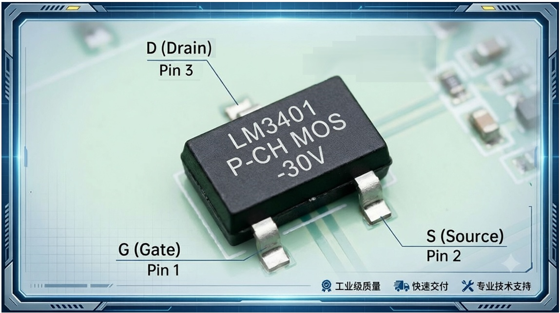
Package |
SOT-23 |
SOT-23 |
SOT-23 |
|
FET type N or P |
P |
P |
P |
|
Drain−to−Source Voltage Vdss |
-30 |
-30 |
-30 |
|
Drain Current 25℃ Id(A) |
-5 √ |
-4 |
-3.7 |
|
Power Dissipation Pd(W) |
2.1 √ |
1.4 |
1.2 |
|
Gate−to−Source Voltage VGS(V) |
12 |
12 |
12 |
|
Gate Threshold Voltage VGS(th) |
-0.5 -0.9 -1.5 |
-0.5 -0.9 -1.3 |
-0.5 -1.0 -1.5 |
|
Rds(on)(10V) (mΩ)Typ |
41 |
41 |
41 |
|
Rds(on)(10V)(mΩ)Max |
50 |
50 |
50 |
|
Rds(on)(4.5V)(mΩ)Typ |
50 |
47 |
47 |
|
Rds(on)(4.5V)(mΩ)Max |
65 |
60 |
60 |
|
Total Gate Charge (Qg) |
14 |
14 |
11.6 |
|
Input Capacitance Ciss |
640 |
645 |
1326 |
|
Gate Resistance Rg |
7 |
7.8 |
7.3 |
|
Thermal Resistance Junction-Ambient RθJA (℃/W) |
60 √ |
100 |
105 |
Data analysis:
A good domestic alternative solution not only achieves high consistency in core parameters but even provides better performance margins in some extreme parameters. For example, the LM3401 excels in continuous drain current (ID reaching -5A), power dissipation (PD reaching 2.1W), and thermal resistance (RθJA as low as 60°C/W), which means it offers stronger surge immunity and lower heat generation under actual operating conditions. Meanwhile, in key high-frequency switching parameters such as on-resistance (RDS(on)) and gate charge (Qg), the LM3401 maintains excellent consistency with the original.
Shanghai Leiditech also offers various MOSFET models for domestic substitution. For example, Leiditech LM2305A can replace Infineon IRLML6401TRPBF, as well as 2305A models from other brands. If you need better supply availability and cost-effectiveness, please contact Shanghai Leiditech sales personnel or the EMC engineer for domestic substitution solutions.
III.Typical applications
Leveraging its low on-resistance, low input capacitance, and fast switching characteristics, the LM3401 is well-suited for handheld and compact applications requiring efficient power management. Two of the most typical application scenarios are supplemented below:
1. Power Management and Load Switch Circuits
l Portable device power and load switches: Used for power management of modules or peripheral circuits in space-constrained, sub-30V systems that require medium current switching.
l DC-DC converters: As a key power switching component in high-efficiency power conversion systems.
2. Battery Protection and Management Circuits
l Battery charge/discharge control: Used as a switching device for the charge or discharge path in single-cell or multi-cell lithium battery applications to achieve efficient battery management.
l Battery protection for handheld devices: Specifically designed to provide reliable switching control for low-power designs in handheld devices such as smartphones.
3. Drive and Control Circuits
l Motor control: Provides stable drive current and switching control for micro motors.
l Backlighting: Used for backlight power control and regulation in devices such as displays.
IV.Selection Summary and Engineering Pitfall Avoidance Guide
When introducing domestic MOSFETs into production, although pin-to-pin physical compatibility can save the trouble of board redesign, it is strongly recommended to conduct small-scale board-level verification before mass production.
Pitfall avoidance suggestions:
During the prototyping phase, it is recommended to use an oscilloscope to capture the VDS and ID waveforms at the moment of turn-on and turn-off, paying close attention to severe voltage spikes or abnormal oscillations. This effectively verifies whether the dynamic parasitic capacitances (Coss, Crss) of the domestic device are within the same order of magnitude as those of the original imported solution. Additionally, it is essential to evaluate the temperature rise based on the actual PCB copper area used for heat sinking, ensuring that the conduction voltage drop under extreme temperatures and the junction temperature during long-term operation remain within safe limits. This guarantees long-term system reliability and ensures a foolproof domestic replacement solution.
